BeebControl>>Interfacing>>Clare |
| CLARE - Control Logo And the Real Environment
I'd never come across any ads, editorial reference or websites for this board and its related add-ons until I acquired this example. This is perhaps because it was aimed squarely at schools and was never publicised outside the educational sphere in the likes of Micro User or Acorn User magazines.
The Clare board was produced by AUCBE (the Advisory Unit for Computer Based Education) of Hatfield, Herts and cost £135 as a package with cables, manual and software. It first appeared in the mid-to-late eighties, making it quite a late entrant in the field of eight-bit computer control. It was designed to be run using the Advisory Unit's Control Logo software, which accompanied the board on disc and added its command set to a previously installed version of Logo by either LCSI/Logotron, Acornsoft or LSL. Apparently, Open University Logo was also supported in early versions.
A 20-way IDC data lead ran from the Clare board to a small adapter card, from which two IDC cables connected to the Beeb's user and printer ports. Use of an adapter card enabled the Clare board to be made compatible with a number of micros such as the RM 380/480Z, Nimbus and Spectrum.
|
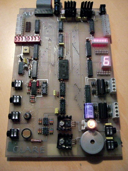 |
| Clare's friendly 'microworld' for computer control
The Clare board is unusual in that it contains an array of indicators, sensors, switches, opto-electronics and motor control, all crammed onto a single board. This all-in-one approach makes the board look a little messy and hard to take in at first, but there's a lot to get to grips with once you've read the manual. The board measures 245mm x 150mm and has two power input sockets at the top. One power socket is for the control electronics and the other supplies a separate circuit for 'noisy' jobs like motor driving. I'm guessing that the original PSU (12v at 2 amps) had two leads fed by a single source, supplying 12v at 1 amp into each socket. The two on-board 7805 voltage regulators would have prevented any noise feedback from the motor driver side. |
 |
This is how AUCBE themselves described the Clare board: "Clare developed out of work done at AUCBE on computer control, based around a buffer box and a series of separate modules. The hardware was conceived as being most of the buffer box modules joined together physically and capable of being selected, controlled and read individually from Logo.
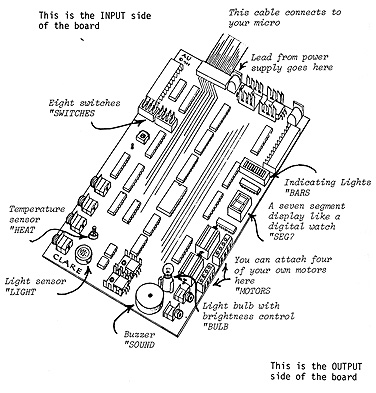
"The final result is an open circuit board with inputs on the left and outputs on the right. The two digital inputs are an 8-bit expansion bus and 8 switches. The four analogue inputs are a light cell, thermistor and two sockets for external sensors. In a similar fashion, the outputs are both digital and analogue, with an 8-bit expansion bus, 8-bar light emitting diodes, a seven-segment display and 8 motor drivers (four pairs). The analogue outputs are a light bulb and a buzzer, these last two also have sockets that can be used to take the outputs off to e.g. motors or external lights."
|
<< Interfacing home All content on this website is © Neil Fazakerley or its originators |
|