and adding a Bridgeport J-head |
| Home [ Major ] J-head | Gallery |
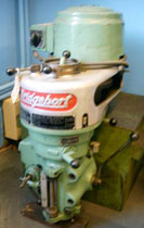
| The original ingredients in 'as found' state. | 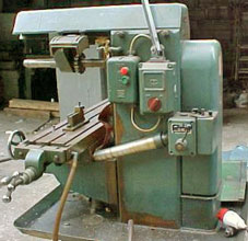 |
 |
 |
|
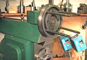
I took micrometer readings across rollers at 1" intervals along the table shears. This produced a graph that looked like Table Mountain, suggesting that full travel would never be possible without a complete re-machine of the ways and a regrind/re-scrape - which was out of the question as this was meant to be a low budget build. But given that the centre section was surprisingly flat and of about the maximum length I could accommodate, I decided to just shorten the table. The plan was to slice the unuseable portions off each end and make use of the worn but flat central section, producing a table about the same length as an M1 but with extra travel of about 18" x 9". This would be ideal for my cramped workshop but would still boast the meatier build and rigidity of the Major. On the other hand, it required some tricky operations as the machine would have to perform the necessary butchery on itself, given that I had no other milling capability. Thanks to a tip-off from Charles Ping on the uk.rec.models.engineering newsgroup, I'd managed to get hold of a loose Bridgeport J-head for a reasonable price, so the first task was to work out how it could be mounted to enable machining of the table. Below left shows the temporary assembly of the J-head to the overarm of the TS mill. |
 |
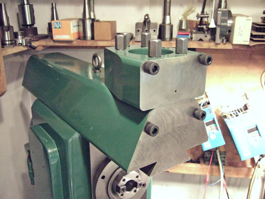 |
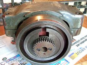
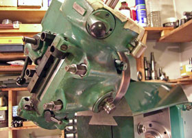
| Head mounting Above right is the finished mounting block after trimming and painting. The cap head screws were just there to keep muck out while I did some repair work on the head and finished its mounting studs. It gives me the option of mounting the head direct for a fixed vertical format, or interposing a plate with circular tee slot to allow the head to swivel in standard BP fashion. And because the head is mounted high on the overarm I can fit the horizontal arbor and arbor support bracket (after some minor clearance mods) and use horizontal mode without disturbing the head. |
| I bandsawed one of the nine cast-in inner 'cells' off the overarm, shortening the length by about 3". This left a full thickness cross-web ready to be faced up flat for the mounting. Shortening also reduced the overarm's rear projection when a head is fitted, making the mill easier to fit into the new corner site I had lined up. | 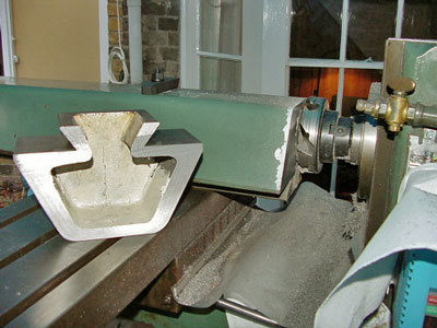 |
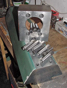 |
| Above you can see the new web being faced with a 4" shell mill fitted to the horizontal splindle, using the machine as a stub miller - a very useful mode. The bolt holes are on standard BP mounting centres of course, the pitch circle being carefully positioned to allow a full thread to be tapped into the longitudinal skin of the cast iron overarm for the bottom bolts. The upper mount is a slice from a 20-inch steel ingot I 'acquired' from a scrap heap a few years back. I think it was once used (along with 10-20 others) as a counterweight on the rear of a crane or similar - hence the large hole present. The five hex 'bolts' in the top surface are actually extended nuts with blind tapped holes at their bottom ends. They are mated with HT cap head screws that feed up from inside the overarm, seating on accurately faced counterbores. |
 |
 |
 | ||
 |
Final mods and mounting
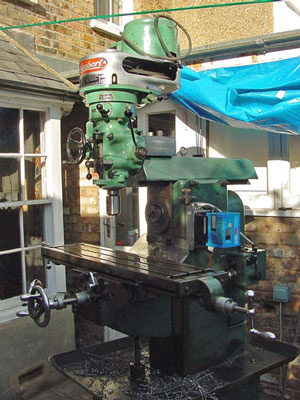
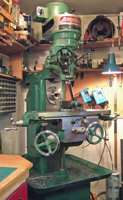
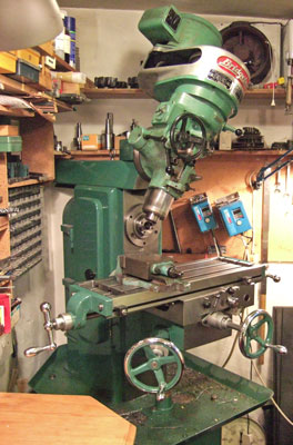
The table has now been trimmed, new pockets cut to match the originals and the mill is finally taking shape indoors in its corner position. As you can see, it's a bit of a beast, although the wide-angle lens tends to enlarge the BP head and shrink the mill's body somewhat. Note how the back corners of the chip tray have been chamfered to allow the mill to be sited right into the angle to save space. The machine has already done useful work, but so far mostly as a horizontal stub miller (a much underestimated format though).
Table travel is around 17" and saddle infeed is 9.5". The two main motors and the separate table traverse motor are run via invertors (VFDs). The 2HP horizontal motor and 1HP vertical motor share a single 2HP inverter via switching, as they have no need to run as a pair.
© neil f, 2008-2018
Home